Introduction
After opening the Amstrad CPC time
capsule again,
I wanted to transfer data off the Amstrad CPC 3" disks that I had,
onto a modern PC for archiving. The modern approach to this seemed to
be to use a Gotek USB Floppy
Emulator,
running FlashFloppy,
connected to the Amstrad CPC as an external drive (drive B:) --
and then use disckit3.com to copy disk sides from drive A: (the
3" drive) to drive B: (the Gotek emulator). So that was what I
set out to do.
Previously I proved the Gotek PC 1.44MB floppy emulator worked on an IBM PC clone so I knew the Gotek hardware worked. And earlier I repaired the two Amstrad CPC 3" drives that I have (by replacing the floppy drive belt), so all that remained to be able to rescue the contents of my 3" discs was to:
Install FlashFloppy onto my Gotek unit;
connect the Gotek unit to one of my Amstrad CPC6128s; and
copy the 3" disc sides onto the Gotek
Disclaimer
If you decide to follow these instructions, please note that you proceed at your own risk. I would advise reading some other install guides as well to be sure you understand the steps before starting. And if you choose the technique involving soldering make sure you are either familiar with soldering safely and know how to avoid creating short circuits, or get the soldering done by someone more experienced. There is also a risk that the FlashFloppy firmware programming might fail and leave you with a dead Gotek board. (I think most firmware programming issues can be fixed by trying the serial loader programming again, but this firmware programming will definitely void your warranty, and may leave you with a dead Gotek.)
If all of these instructions seem too complicated for you, note that there are several vendors online, including TechExpress, who will sell you Gotek units already pre-programmed with FlashFloppy (or HxC firmware for the Gotek) in a ready to use package. I chose to do it myself, as described below, because I wanted to understand the whole process, and was already at least somewhat familiar with all the steps involved.
Preparing to install FlashFloppy
There are two methods to install FlashFloppy onto a Gotek unit:
Install via serial loader using a USB to TTL serial cable; or
Install via Device Firmware Update (DFU) through the USB port on the Gotek, which requires a USB-A to USB-A male to male cable (relatively uncommon; people mostly seem to have made them by cutting the ends of other cables and soldering them together).
Since I already had a USB to TTL serial cable, which I had previously used for programming another ARM STM32 chip, and I knew from reviews that the Gotek contained an ARM STM32F105 chip, my plan was to program FlashFloppy onto the Gotek using the serial loader.
To be able to use the serial loader, it is necessary to be able to connect up to the serial pins in the circuit board and short two pins together to hold the STM32F105 in programming mode. These pins appear on a 8 pin header at the back of the board (actual photo in another programming article), near the power connector -- but on most boards do not have any pin headers on them. (My board seemed to have 9 pin headers: 5 + 4, but the relevant pins seemed to be in the same position.)
If you happen to have good probe connectors that can reliably connect into the through holes directly, you might be able do this without any soldering. Otherwise your best options are either to solder in some pin headers, or to solder in some wires to connect to your USB to TTL programmer and for the programming mode jumper. I did not have good probe connectors, and wanted an option that would make it easier to reprogram if required, so I chose to solder in a set of pin headers. The case can be opened with just two screws at the top centre, and then the circuit board will just lift out. The through holes are drilled to fit standard 0.1" (2.54mm) pitch pin header strips, which are easily obtained from hobby electronics stores. Soldering in the pin headers only takes a few minutes for anyone with even modest soldering skills -- I have only soldered a few things before, and was working with a very old and crusty soldering iron, and it still only took me a few minutes and worked first time. (I did use a multimeter to both continuity check for shorts before/after soldering in the pin header, and also check for continuity to the points I traced each header going to on the board to verify my soldering. I also tested the Gotek on my IBM PC clone floppy setup one more time before moving on to programming the firmware, and was glad to see it still worked just as before. If you have not soldered at all perhaps find a friend skilled in soldering and ask them a favour -- it will probably only take one with the right skills and equipment about 5 minutes to solder in a handful of 0.1" pin headers for you.)
Installing FlashFloppy
Once the Gotek circuit board is ready for programming, the next step is to disconnect it from everything else (including disconnect it from power), then connect it up to the USB to TTL serial interface and program in the FlashFloppy firmware to replace the stock firmware.
To do this:
Download the FlashFloppy binary installation, most likely the latest version which was 0.9.21a last week when I installed, and seems to be 0.9.22a as I write (0.9.22a apparently adds some more drive formats, and additional display/control functions); I have not tried 0.9.22a myself, and the examples below are with 0.9.21a that I used.
From the
.zipfile you download, extract out the.hexfile that is needed for initial serial programming:unzip -j flashfloppy_v0.9.21a.zip flashfloppy_v0.9.21a/FF_Gotek-v0.9.21a.hexInstall the
stm32flashtool if you do not already have it installed:sudo apt-get install stm32flashConnect up the programming jumper and USB to TTL interface to the Gotek board, making sure nothing else is connected to the Gotek. Looking at the back of the Gotek board, with the power connector facing you on the left and the floppy data connector facing you on the right, connect up:
A jumper on the left most two pins in the row furthest from the power connector (to put it in "programming mode"). There are some suitable sized jumpers on the configuration jumper section and you can borrow one of those providing you remember where it came from and put it back later.
Connect the "RX" lead of your USB to TTL adapter to the pin next to that jumper (the "TX" pin of the ARM STM32F105)
Connect the "TX" lead of your USB to TTL adapter to the pin next to the RX one (the "RX" pin of your ARM STM32F105)
This should give you a row:
=== RX TX o
    o  o  o
with the other pins not used for this purpose (where
RXandTXhere are the leads from your USB to TTL adapter, and===is the jumper of the left most pins).Connect Ground and +5V to the power connector of the Gotek (these also appear on the pin header pins if you soldered them all in, but the floppy connector is easier to describe; the 3.5" floppy power connector is a 4 pin polarised Berg connector, a LP4 -- note the signal order shown at that page is the order for the female connector on the power supply, and thus is mirror reversed from the male connector on the floppy drive so that they match up correctly).
Looking from the back of the power connector (with it on the back left of the Gotek, as noted above), you want to:
Connect the ground lead to one of the middle pins of the connector (eg, second from the left)
Connect the +5V lead to the right most pin of the connector, furthest from the "programming mode" jumper you installed above (and nearest to the 34-pin floppy data connector).
This should give you:
o GND o +5Von the power connector looking at it from the back. Together you get:
=== RX TX o
    o  o  o

o GND o +5V
at the back left of the Gotek, looking at it from the back.
I used the GND / +5V from my USB to TTL adapter (thus powering it from USB power), and that seemed to work okay (and I have done that for programming other ARM STM32 chips).
Double and triple check your cabling against the photos on the FlashFloppy serial programming instructions or the Cortex firmware programming instructions to make sure you have your cabling right.
When you are happy with your cabling (and that your soldering did not create any shorts!), plus the USB to TTL interface into your computer. You should see, eg,
/dev/ttyUSB0appear after a few seconds.Wait a few more seconds (eg, another 15 seconds) to give the ARM STM32 chip time to initialise into programming mode.
Check that the programmer can see the ARM STM32F105:
ewen@parthenon:/src/gotek/FlashFloppy/release$ stm32flash /dev/ttyUSB0
stm32flash 0.5

http://stm32flash.sourceforge.net/

Interface serial_posix: 57600 8E1
Version      : 0x22
Option 1     : 0x00
Option 2     : 0x00
Device ID    : 0x0418 (STM32F105xx/F107xx)
- RAM        : 64KiB  (4096b reserved by bootloader)
- Flash      : 256KiB (size first sector: 2x2048)
- Option RAM : 16b
- System RAM : 18KiB

ewen@parthenon:/src/gotek/FlashFloppy/release$
As the Gotek is supplied, the ARM STM32F105 is protected, so you cannot read the firmware back (ie, reading will fail with a NACK) or write to it:
ewen@parthenon:/src/gotek/FlashFloppy/release$ stm32flash -r gotek-default.hex /dev/ttyUSB0
stm32flash 0.5

http://stm32flash.sourceforge.net/

Interface serial_posix: 57600 8E1
Version      : 0x22
Option 1     : 0x00
Option 2     : 0x00
Device ID    : 0x0418 (STM32F105xx/F107xx)
- RAM        : 64KiB  (4096b reserved by bootloader)
- Flash      : 256KiB (size first sector: 2x2048)
- Option RAM : 16b
- System RAM : 18KiB
Memory read
Got NACK from device on command 0x11
Failed to read memory at address 0x08000000, target write-protected?

ewen@parthenon:/src/gotek/FlashFloppy/release$
So the next step is to remove the protection, so that the ARM STM32 can be written. This also removes the factory firmware, and so this is the step where you commit yourself to going forward with FlashFloppy or HxC or another third party firmware. To remove the protection:
ewen@parthenon:/src/gotek/FlashFloppy/release$ stm32flash -k /dev/ttyUSB0
stm32flash 0.5

http://stm32flash.sourceforge.net/

Interface serial_posix: 57600 8E1
Version      : 0x22
Option 1     : 0x00
Option 2     : 0x00
Device ID    : 0x0418 (STM32F105xx/F107xx)
- RAM        : 64KiB  (4096b reserved by bootloader)
- Flash      : 256KiB (size first sector: 2x2048)
- Option RAM : 16b
- System RAM : 18KiB
Read-UnProtecting flash
Done.

ewen@parthenon:/src/gotek/FlashFloppy/release$
At this point it seems like the ARM STM32F105 restarts again, and you will need to wait some seconds for it to be ready again. In my case it also stopped responding to serial programming commands, which apparently is a known issue. So after waiting a couple of minutes for it to work properly, I then unplugged the USB to TTL adapter from the computer, waited 10 seconds, then plugged it back in again. And checked with the identification command (
stm32flash /dev/ttyUSB0as above) that it was responding again before proceeding (after giving it some time to boot into programming mode again).Now the STM32F105 is unprotected, and empty, we can flash the FlashFloppy firmware onto it:
ewen@parthenon:/src/gotek/FlashFloppy/release$ stm32flash -vw FF_Gotek-v0.9.21a.hex /dev/ttyUSB0
stm32flash 0.5

http://stm32flash.sourceforge.net/

Using Parser : Intel HEX
Interface serial_posix: 57600 8E1
Version      : 0x22
Option 1     : 0x00
Option 2     : 0x00
Device ID    : 0x0418 (STM32F105xx/F107xx)
- RAM        : 64KiB  (4096b reserved by bootloader)
- Flash      : 256KiB (size first sector: 2x2048)
- Option RAM : 16b
- System RAM : 18KiB
Write to memory
Erasing memory
Wrote and verified address 0x08016ba0 (100.00%) Done.

ewen@parthenon:/src/gotek/FlashFloppy/release$
The process took about 1-2 minutes.
I then waited a little while for that to settle, and double checked the STM32F105 was still responding:
ewen@parthenon:/src/gotek/FlashFloppy/release$ stm32flash /dev/ttyUSB0
stm32flash 0.5

http://stm32flash.sourceforge.net/

Interface serial_posix: 57600 8E1
Version      : 0x22
Option 1     : 0x00
Option 2     : 0x00
Device ID    : 0x0418 (STM32F105xx/F107xx)
- RAM        : 64KiB  (4096b reserved by bootloader)
- Flash      : 256KiB (size first sector: 2x2048)
- Option RAM : 16b
- System RAM : 18KiB

ewen@parthenon:/src/gotek/FlashFloppy/release$
At this point the firmware programming is done. Unplug the USB to TTL adapter from the computer, and power down the Gotek (if you were powering it separately). Then unplug the USB to TTL adapter from the programming headers, remove the programming jumper (and if you borrowed it from somewhere else, put it back where you found it).
(Note that Firmware Updates of FlashFloppy are much
simpler, as
it supports programming an update straight from the USB stick; this
difficult serial programming process is only needed to replace the
factory stock firmware with FlashFloppy the very first time. Updates
are basically: copy a .upd firmware update file onto the USB stick,
removing all other .upd files, then power the Gotek on with the
USB stick inserted and holding down both buttons. When "UPD"
is displayed on the 7-segment LEDs, release both buttons, and wait
for the Gotek to program itself and reboot into the new version. I suspect
this only works to go to newer versions; rolling back to older versions
probably requires serial programming or DFU.)
Testing the Gotek with FlashFloppy on an IBM PC clone
FlashFloppy can be connected to an IBM PC floppy interface, or to other micro computer floppy interfaces (most of which are closer to the original Shugart 34-pin interface). I wanted to test my Gotek with FlashFloppy on the same IBM PC clone I had used for testing the Gotek hardware, to make sure the hardware was still working before moving on to connecting it to the Amstrad CPC6128.
To use FlashFloppy on the Gotek with an IBM PC you need:
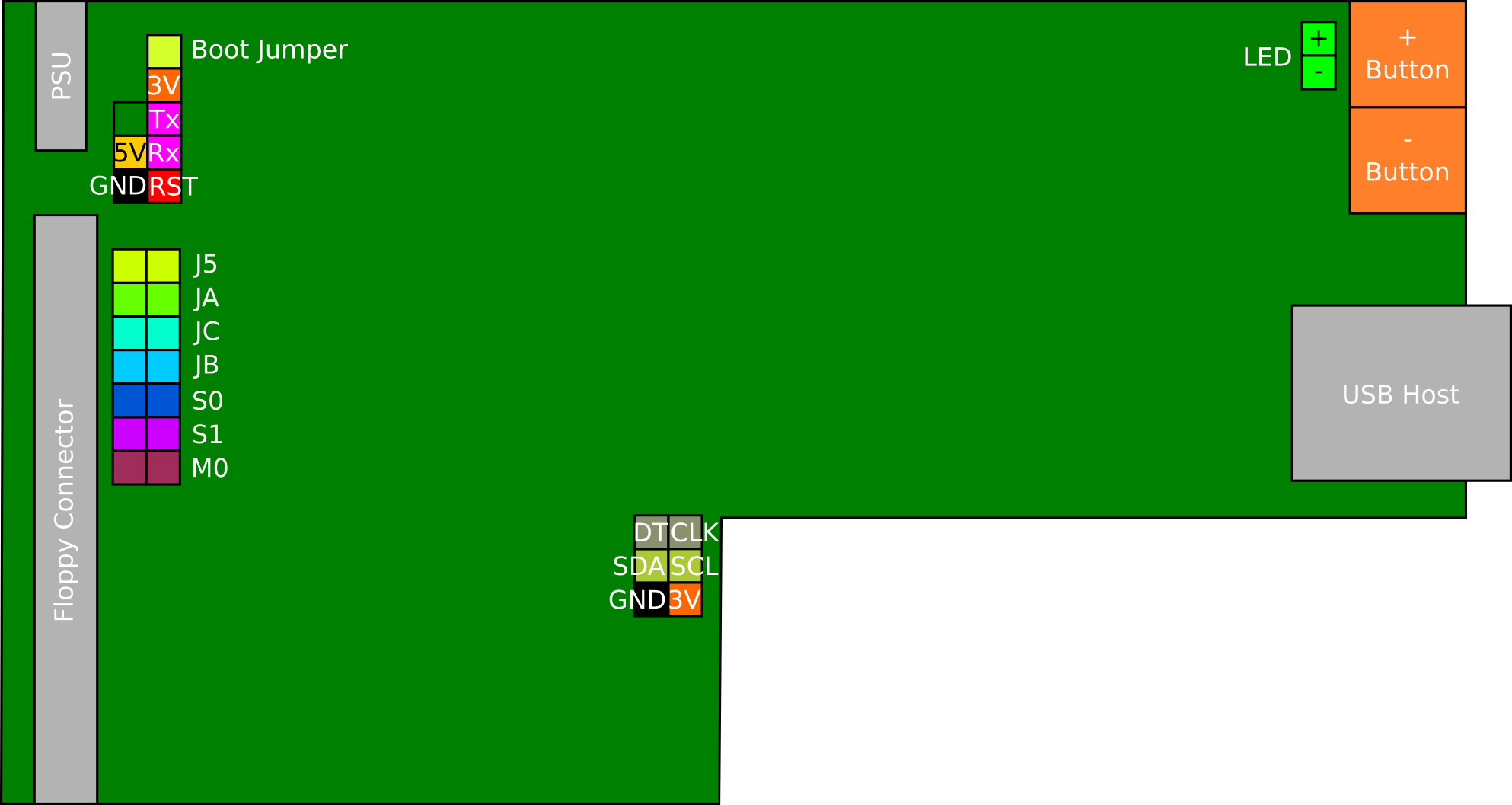
A jumper on the "JC" pins to select IBM PC floppy interface mode (eg, drive change rather than disk ready signals)
A jumper on the "S1" pins to select drive 1, as the IBM PC uses a twisted floppy cable and the position on the cable to select the drive letter rather than the drive jumper position -- and I had a twisted PC floppy cable in use.
The USB stick formatted as a FAT32 drive (super floppy mode). This is commonly how they arrive from the shop, but not how the default Gotek firmware expects them to be formatted.
Copy the
FF.CFGexample (FF.CFGdocumentation) onto the USB stick, in the root directory. The exampleFF.CFGworks okay with the IBM PC for an initial test, so no changes are required at this point.Copy a test floppy image (eg, the uncompressed version of the compressed FreeDOS 1.44MB boot floppy, that I used when testing the default Gotek firmware) onto the USB stick as
DSKA0000.IMG, eg:wget http://www.fdos.org/bootdisks/autogen/FDSTD.144.imz unzip FDSTD.144.imz cp -p FDSTD.144 /media/ewen/GOTEK/DSKA0000.IMGEject the USB stick from the computer, and plug it into the Gotek.
Plug the Gotek unit into the IBM PC clone floppy interface/power, and power the IBM PC on (and thus the Gotek on).
When the Gotek first powers on you should briefly see "F F" on
the LED display, followed by a virtual floppy image number (000).
All going well, the IBM PC should be able to boot FreeDOS, from the
virtual floppy image provided by the Gotek running the FlashFloppy
firmware. If that works, the Gotek is successfully upgraded to
the FlashFloppy firmware and still supports the IBM PC floppy mode
of the factory firmware.
Connecting the Gotek with FlashFloppy to the Amstrad CPC6128
The Amstrad CPC6128 has an external floppy connector ("B:"), which is a 34-pin connector laid out almost like the Shugart 34 pin floppy connector de facto standard. The only significant difference is that the signals are 180 degrees reversed on the Amstrad CPC6128. This means that you need:
A straight through (no twists) 34-pin floppy cable (or to use the section of the cable which does not have twists and accept a little loss in signal quality)
Which has a 34-pin dual 0.1" IDC connectors (ie, like on the Gotek)
And a 34-pin connector to suit the Amstrad CPC, in my case a PCB edge connector.
Without any orientation guides, or blocked holes to force you to connect it a certain way, as we need to connect the whole cable 180 degrees out of straight-through alignment.
See this guide to Spectrum +3 related Floppy Connectors for an illustration of the connectors required (Amstrad were also making the Spectrum computers by the time the Spectrum +3 came out). Note that the signal 34 (ready) modifications there are not needed with the Gotek running FlashFloppy as the Gotek can be configured to provide the required Ready signal directly.
I happened to have a lot of old IBM PC floppy cables, which had both 34-pin dual 0.1" IDC connectors (for the motherboard and 3.5" drives) and 34-pin edge connectors (for 5.25" drives on them), and simply used the straight (untwisted) section of that cable. (There is a slight signal degradation in having excess cable hanging off the end beyond what you are using, due to it being after the transmission line terminator. But it seemed to work "okay" for me. Once you have it working a permanent solution would be to cut the final unused connectors off the floppy cable if you are not going to use them for something else; several Amstrad CPC users have invented ways to join signals via those other connectors.)
For me the most time consuming challenge was finding a way to power the Gotek when it was connected to the Amstrad CPC. My plan was to use an external (SCSI) drive case (of which I have several) and a 4-pin Molex (5.25" drive) to 4-pin Berg (3.5" drive) power adapter... of which I thought I had several as well. Unfortunately in reality it actually took me 90 minutes to even find one 4-pin Molex (5.25" drive) to 4-pin Berg (3.5" drive) power adapter around the house. Finding it involved opening a lot of boxes (and PC cases) that hadn't been opened for a decade :-( (Those adapters are still available new, at least from Ebay / AliBaba, so I might pick up a couple more just to have some where I know where they are! Another option would be an IBM PC power supply which comes with the right power connector, but note that most ATX power supplies need some persuasion to turn on without a PC motherboard connected -- and the first few IBM PC power supplies I tried were dead/not working any more. I did also find someone who kludged together a USB charger cable and a 3.5" power connector, to use a standard USB charger to power the Gotek; so with some electronics knowledge that could be an option.)
Having got all the right cables together, to connect the Gotek with Flash Floppy to the Amstrad CPC6128:
Power everything off (Amstrad CPC6128, Gotek, etc)
Unplug the "JC" jumper on the Gotek (if you connected it for testing on an IBM PC), but make sure the "S1" jumper is connected so it is drive 1 (ie, drive "
B:"). There should not be any other jumpers connected.Make sure the Amstrad CPC6128 edge connector is clean (seriously I wasted a lot of time, and had a lot of frustration, because I was trying to test on the old donated Amstrad CPC6128 which had accumulated a lot of dust over the years... and I had only partly cleaned it; the floppy interaction was very confusing with an unclean connector!).
Connect the floppy data cable to the Gotek, noting that pin 1 is on the right as you look at the Gotek from the front (ie, from the USB stick side). Connect the red wire of the floppy cable to pin 1.
Connect the floppy data cable to the Amstrad CPC6128, ensuring that the red wire of the floppy cable ends up connected to pin 34, which is on the left as you look at the Amstrad CPC6128 from a normal typing position. This puts a 180 degree twist in the whole cable, necessary to make the signals line up due to the Amstrad CPC6128 floppy connector numbering.
Plug in the power connector you are using for the Gotek, and turn it on.
Plug in the Amstrad CPC6128 power and turn it on.
All going well the Amstrad CPC6128 A: drive works okay, and the Gotek shows, eg, "F F" briefly on boot and then, eg "000" and is ready. (If the Amstrad CPC6128 A: drive does not work, chances are the external floppy connector is upside down, as this will ground all the signals, due to one side of the connector being ground, and many of those signals are shared with the internal drive, A:, too.)
Richard Oxley has two good blog posts on the Amstrad CPC6128 floppy interface technical details: HxC Floppy Drive Emulator, and Jumpers! In Adventure with Floppy Cables!. The latter explains how some of the "short this pair of wires" extra options work, including being able to make the external drive replace drive A: (by impairing the drive select line to the internal drive).
Preparing the USB stick for the Gotek on the Amstrad CPC6128
For my purpose of copying Amstrad CPC6128 3" discs onto the Gotek unit, the USB stick for the Gotek needs a bit of advanced preparation because:
We want to be very sure which floppy image we are writing to when aiming to archive a set of Amstrad CPC6128 3" disc (sides), because otherwise we might make a great copy of a disc... and then overwrite it minutes later by accident.
The only indicator (on stock Gotek hardware) of which floppy image is selected, is the 3 digit 7-segment LED.
So we want to have a predictable mapping from the filename on the USB stick to the 3 digit 7-segment number displayed, and vice versa.
FlashFloppy can only detect, and write to, disk images that already exist on the USB stick.
FlashFloppy can only write to the virtual floppy in the same format (including same sectors) that already exist; it does not support "formatting" a virtual floppy disk with new sectors. Since the Amstrad CPC uses different sector number for "Data" and "System" format discs, this requires some advance preparation to be able to copy both.
So we both need to put FlashFloppy into a predictable order mode, which
we do by editing FF.CFG on the USB stick so that it says:
nav-mode = indexed
which means that it expects to find files:
DISKA0000.DSK
DISKA0001.DSK
and so on (including other extensions that it supports), and builds a list of the ones available when it powers up and lets you cycle amongst those -- displaying the last three digits of the filename as the value on the 3-digit 7-segment LED display. So we can now tell exactly which file is selected.
Then we need a bunch of blank disk images, in Amstrad CPC System format (a few) and Amstrad CPC Data format (many), since these both have to exist and have to be in the right floppy format to be able to copy the physical 3" disc directly onto them.
To create these disk images, I used dskform from
libdsk to format some blank
disk images. I chose that tool as it seemed to default to creating
Amstrad CPC standard (ie not extended) .dsk files, which seemed
likely to maximise compatibility with other tools later.
I first created a blank Data .dsk image, and a blank System .dsk
image:
dskform -format cpcdata -type dsk cpc-data.dsk
dskform -format cpcsys -type dsk cpc-sys.dsk
and then used cpcxfs (written by Kevin Thacker, 2016 download
site) to verify the disk formats were as I expected. I got:
$ cpcxfs cpc-data.dsk -s
Found format "DATA" matching disk image format

Image File     : cpc-data.dsk
Image Type     : STANDARD
Format         : DATA (Data Format)

CP/M           : No
Current user   : 0

Capacity       : 180 Blocks = 184320 Bytes
Directory      : 2 Blocks
Allocated      : 2 Blocks = 2048 Bytes =   1.1%
Free           : 177 Blocks = 181248 Bytes =  98.9%

Prompt="cpcfs> ";  Local directory="/tmp"
Verbosity=9;  Page length=25;  Mode=Binary;  Force=-off-

$
and:
$ cpcxfs cpc-sys.dsk -s
Found format "SYSTEM" matching disk image format

Image File     : cpc-sys.dsk
Image Type     : STANDARD
Format         : SYSTEM (System Format)

CP/M           : Yes
Current user   : 0

Capacity       : 171 Blocks = 175104 Bytes
Directory      : 2 Blocks
Allocated      : 2 Blocks = 2048 Bytes =   1.2%
Free           : 168 Blocks = 172032 Bytes =  98.8%

Prompt="cpcfs> ";  Local directory="/tmp"
Verbosity=9;  Page length=25;  Mode=Binary;  Force=-off-

$
so that looked good.
Then I decided to use the 1xx disk images to copy the Amstrad CPC6128
original system disks (two System disc sides -- 1 and 4, and two Data
disc sides -- 2 and 3; disc sides 1 and 4 hold CPM/Plus and CPM/2.2
for the Amstrad CPC6128 respectively). And to use 2xx disk images
to hold Data disk sides. When I need some more System disk sides (likely
as I had some custom boot discs), I will made some more copies of
cpc-sys.dsk in the 3xx range.
To set up the USB stick I did:
# 1xx -- Amstrad CPC official boot discs
cp -p cpc-sys.dsk DSKA0100.DSK
cp -p cpc-data.dsk DSKA0101.DSK
cp -p cpc-data.dsk DSKA0102.DSK
cp -p cpc-sys.dsk DSKA0103.DSK

# 2xx -- Amstrad CPC data discs
for SEQ in $(seq -f "%04.0f" 200 299); do
    cp -p cpc-data.dsk DSKA${SEQ}.DSK;
done
And then removed the OS X created files, and ejected the USB stick:
rm -r .Spotlight-V100 .Trashes .fseventsd/; cd; eject /Volumes/GOTEK
Once that was done, the USB stick was ready for the Gotek (with FlashFloppy firmware) to help with archiving the disks.
Archiving the 3" discs
To archive the 3" discs, I plugged the prepared USB stick into the Gotek, turned on the Gotek and the Amstrad CPC6128, and then booted into CP/M Plus using 3" boot disc:
|cpm
The CP/M Plus boot banner should show two drives connected.
Once CP/M Plus booted, I then ran:
disckit3
to start the supplied Amstrad CPC6128 disk copy program. (See also a history of the DiscKit program for the Amstrad CPC and PCW range.)
Then I used the buttons on the Gotek to select drive image 100, the
first of the images for the official Amstrad CPC6128 boot disks -- a
System disk image. The floppy auto-mounts after a couple of seconds.
The disk image can be copied by choosing:
If you are copying something other than the system disc itself, insert it now, and pick another Gotek floppy image number using the buttons on the Gotek. I would very strongly suggest write protecting the source 3" disc!
f7to copy a discf8to copy fromA:(the 3" internal drive)f6to copy toB:(the external Gotek)yto confirm the copy should proceed (this is the last chance to check you have the correct Gotek image selected, including one that is of the correct disc formatting type!)
The two drive copy proceeds in a similar manner to the single drive disc copy except that you do not have to swap discs at all. If anything it seems like the Gotek is slower than the physical 3" floppy disc at reading/writing -- but that is understandable given that it is a CPU emulating a floppy drive! (The Gotek feels about 33% slower than a real 3" floppy disc, to me, but it is still very convenient to use.)
The main challenge with this process (other than ensuring the Gotek
points at a correctly pre-formatted image before you overwrite it!)
is handling the situation at the end when disckit3 tells you to
"remove both discs" and press any key. The Gotek does not have an
"eject" button (at least by default). I found the easiest solution
was to remove the 3" disc in drive A:, and then press the "next
floppy" button on the Gotek and then immediately the space bar
on the keyboard to tell disckit3 "check now" -- and the floppy
was detected as ejected (because the Gotek does not auto mount it
for 2 seconds -- leaving a small "no floppy present" window that
we need).
Conveniently that process lines us up for copying the next floppy side,
and we can just insert the next 3" disc side, and press y to copy it,
and so on.
The other important point with this process is to keep detailed notes
on which disc image number contains which floppy disc copy, so you can
find them again later (and avoid overwriting them). I plan to keep
notes on paper, and then once I have copied a batch of discs to turn
off the Amstrad CPC6128/Gotek, and copy the images off the Gotek USB
stick onto my computer for archiving with a more detailed filename,
eg, DSKA0200-Contents_Of_Disk_Label.DSK, so I will be able to identify
them later.
Now all I need to do is copy the other 120 or so sides of the 60-ish Amstrad CPC6128 3" discs that I have. With luck that only takes a few hours -- much less time than getting to the point where I was in a position to copy them!